
SUMMARY:
The figure below summarizes the major components of the heat pump system and their respective functions within the system.

INTRODUCTION
A heat pump is a mechanical system that can provide both cooling and heating within a single entity. Unlike an air conditioner, a heat pump can provide heating in winter conditions. The heat pump system can be divided into three major groups: an indoor unit, an outdoor unit, and controls. All three components and their specific function to complete the system have been summarized below.
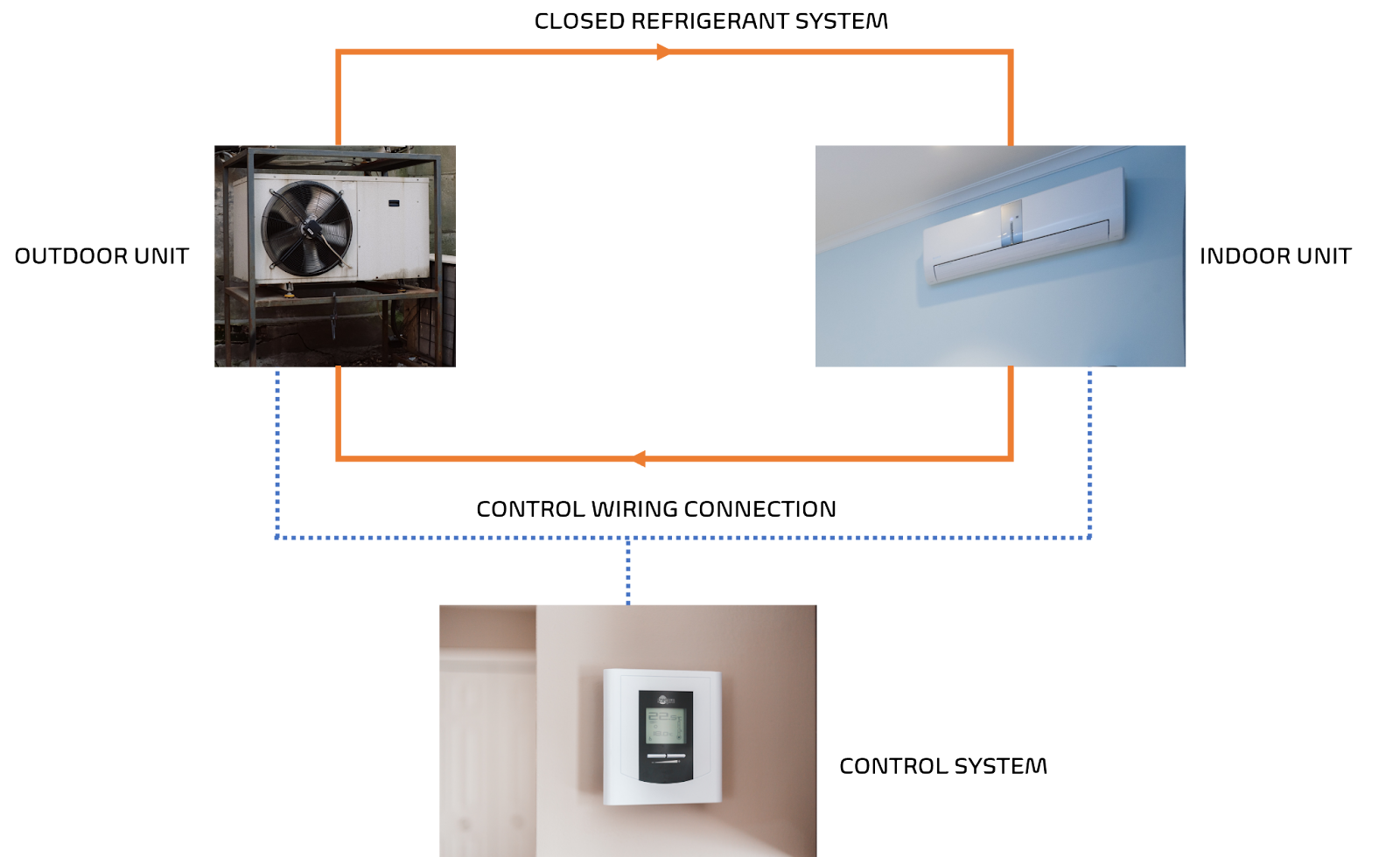
FIGURE 1: Major components of a heat pump system
- INDOOR UNIT
The indoor unit is an air handling unit located within the building. The most common components included within the indoor units are a heat exchanger, fan, air filter, and drain system.

Figure 2: Components of Indoor Unit
The heat exchangers have a refrigerant following through them. The fan directs the air within the room through the heat exchanger. The larger surface area of the heat exchanger allows the efficient transfer of heat between the air and the flowing refrigerant. The temperature of the refrigerant flowing through the heat exchanger depends on the user-defined conditions of the room. For example, the refrigerant enters the heat exchanger in a cooler liquid form during summer when cool air is required. The hot air within the given space will transfer the heat to the cold refrigerant gas. As a result, the air will be relatively cooler as expected while the refrigerant gains heat energy. Consequently, the indoor unit will supply desired cold air to the room. In the meantime, refrigerant gas will leave the heat exchanger in a hotter gaseous form.
Similarly, the refrigerant entering the heat exchanger will be in hot gaseous form during winter when heating is required. The heat gets transferred to the cold air within the room. As a result, warm air will be supplied to the room by the indoor unit, while refrigerant leaving the heat exchanger will be relatively cold.
The heat exchanger and fans work together to provide the heating and cooling as required, while air filters and drain systems support providing clean air with appropriate humidity. The air filters are placed to filter the air and maintain the air quality.
The comfortable temperature during the summer is around 75 degrees with a relative humidity of 50%. In such conditions, the indoor unit typically supplies the air at around 55 F degrees. When cooling the air using the above-mentioned conditions (check psychometrics), water vapor will condensate into water droplets. The drain system collects this water and allows an option for proper disposal. The next section discusses the outdoor unit.
- Outdoor Units
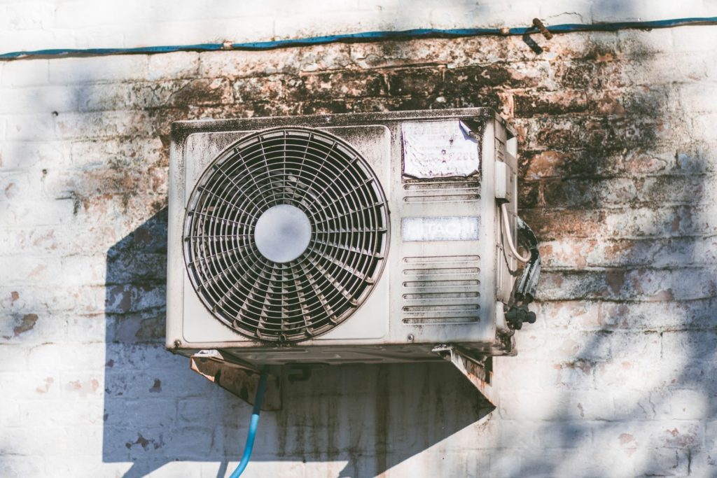
As the name suggests, the outdoor units are designed to be placed outside, exposed to the atmosphere. The most common components included within the outdoor units are a heat exchanger, fan, compressor, and expansion valve.
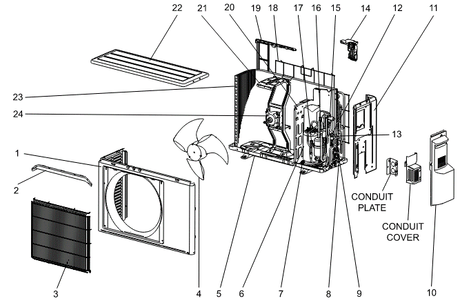
| Part Number | Part Name | Part Number | Part Name | Part Number | Part Name |
| 1 | Cabinet | 9 | Stop Valve | 17 | Service Port |
| 2 | Ice Guard | 10 | Service Panel | 18 | Wire Net |
| 3 | Grille | 11 | Back panel | 19 | Condenser Net |
| 4 | Propeller Fan | 12 | Expansion Valve | 20 | Separator |
| 5 | Base | 13 | Exp. Valve Coil | 21 | Motor Support |
| 6 | Compressor | 14 | Thermo Holder | 22 | Top Panel |
| 7 | Comp. Rubber Set | 15 | 4-Way Valve | 23 | Heat Exchanger |
| 8 | Stop Valve | 16 | Service Port | 24 | Fan Motor |
Figure 3: Components of Outdoor Unit
The heat exchanger and fan work similarly for outdoor units like the way discussed for indoor units. The heat exchangers have a refrigerant following through them. The fan directs the air in the atmosphere through the heat exchanger to ensure efficient transfer of heat between the air and the flowing refrigerant. The temperature of the refrigerant entering the heat exchanger of the outdoor units is exactly opposite to the temperature of the refrigerant entering the heat exchanger of the indoor units. The refrigerant enters the heat exchanger in a hotter form during summer and it enters in a colder form during winter.
In addition to the fan and heat exchanger, the outdoor unit includes a compressor and expansion tank. The compressor is the mechanical equipment with maximum electrical demand in a heat pump system. It is the major component in moving and controlling the refrigerant. It uses electrical energy to provide the required energy for the refrigerant to move throughout the heat pump system. The refrigerant entering the heat compressor is called the suction line and the refrigerant leaving is called the discharge line. The refrigerant enters the compressor as low pressure, low-temperature vapor and exits the compressor as high pressure, high-temperature vapor. After passing the compressor, the refrigerant is passed to the heat exchanger. The refrigerant leaves the heat exchanger as a high-pressure, low-temperature liquid. The refrigerant transfers significant amounts of heat (As the latent transfer is significantly higher than sensible transfer)in the heat exchanger as it changes its phase from gas to liquid. The heat exchanger right after the compressor is called the condenser. Based on cooling or heating requirements, the condenser can be either within the outdoor unit or within the indoor unit. When cooling is required, the condenser is placed outside while the condenser is placed inside during heating requirements.
The expansion valve, also called, the throttling device, works exactly opposite the compressor. The refrigerant enters the expansion valve as a high-pressure, low-temperature liquid and leaves as a low-pressure, low-temperature liquid. This is important because refrigerant flows through a heat exchanger after passing the throttling valve where phase change occurs again allowing for significant heat transfer. This heat exchanger is called an evaporator where refrigerant enters as a liquid where it absorbs heat and exits as gas. The heat exchanger in the indoor unit during summer is the evaporator.
The above-mentioned systems are the major mechanical components within the indoor and outdoor units. The operation of these units such as the speed of the fan, and the flow rate of the refrigerant (supplied by the compressor), is controlled by how much heating or cooling is required. This is where the control system is important.
- Control System
It is often suggested that ‘the make or break of an HVAC system depends on controls’. The description of how the control system works for different modes has been discussed in this section.
The control system for ventilation measures the amount of atmospheric air that enters the system. It controls the volume of the air to allow for proper mixing of the atmospheric air with the return air within the conditioned space. The control system stops the atmospheric air or activates a secondary heating system to heat the atmospheric air when a low temperature of mixed air is measured. This is important because the too low temperature of the air might freeze the fluid flowing through the heat exchanger. Likewise, for cooling and heating, the control system cycles the compressor and expansion valve to maintain the required temperature of the refrigerant gas. When the heating or cooling load is higher, the control system engages the compressor to work at a higher capacity which increases the temperature of the refrigerant exiting the compressor. Similarly, for the fan, the control system adjusts the volume of air for maintenance of appropriate duct and space pressure. Moreover, it reduces the operating cost of the system and enhances overall system performance.

Figure 4: An example of a wall mounted Thermostat
The above system sums up the major components of a heat pump system and their respective operation. To understand how these components work together to complete the cycle refer to this link.